Multi-Chassis Link Aggregation (M-LAG) Configuration Guide
Introduction
Modern enterprise networks must maintain continuous operation, even when hardware failures occur. Traditionally, this resilience has been achieved using two methods: spanning tree–based redundancy and chassis stacking. However, both approaches introduce limitations that become more pronounced as availability requirements increase.
This guide discusses Multi-Chassis Link Aggregation (M-LAG), a technology that provides both link and device redundancy without the constraints of traditional methods and describes its configuration and operation on TP-Link Omada Campus Layer 3 switches.
What problem does MLAG solve?
Every network designer faces the same question: how do you build a reliable access or aggregation layer without creating a single point of failure?
The usual answers are active/standby uplinks, Spanning Tree Protocol (STP), or chassis stacking. Even though they all work, each comes with its own costs:
- Active/standby uplinks: Only one link does the work, so you lose half your bandwidth right away. And when something fails, it can take a few seconds for traffic to switch over. This is usually long enough for users to notice packet loss.
- Spanning Tree Protocol (STP): When the network changes, STP needs time to balance itself out. Convergence can take tens of seconds, and those blocked ports just sit there, wasting potential capacity.
- Chassis stacking: This makes multiple switches act like one device under a single master. This looks simple enough, but the whole stack depends on that master. If it fails or goes down, even due to something as simple as a software upgrade, the entire stack is affected.
M-LAG eliminates these limitations. It allows two independent switches to appear as a single logical Link Aggregation Group (LAG) to connected devices while maintaining separate control planes. The result is high availability and redundancy, without sacrificing bandwidth or introducing shared points of failure.
How does M-LAG compare to Stacking?
Stacking and M-LAG serve similar goals but differ fundamentally in architecture. The comparison below highlights the most important distinctions:
|
Characteristic |
Traditional Stacking |
M-LAG |
|
Control plane |
Shared, one master controls all units |
Independent, each switch runs its own control plane |
|
Single point of failure |
Yes, master failure or upgrade affects all units |
No, each device fails independently |
|
Software upgrades |
Whole-stack upgrade required; extended outage likely |
Rolling upgrade, one device at a time, minimal disruption |
|
Bandwidth utilisation |
All links can be active simultaneously |
All links can be active simultaneously |
|
Loop prevention |
Handled internally by the stack |
Handled by M-LAG protocol rules across peer devices |
|
Configuration sync |
Automatic across all stack members |
Manual, administrator must mirror M-LAG-relevant settings |
|
Scalability |
Limited to stack maximum (vendor-defined) |
Two devices only. But you can cascade multiple M-LAG groups, providing better scalability than Physical Stacking. |
The key takeaway: M-LAG provides redundancy similar to stacking while keeping each device's failure domain isolated, making upgrades and replacements far less disruptive.
Core Concepts
Before working with M-LAG configurations, it is important to understand the specific vocabulary used by the protocol. Each term describes a distinct component or role within the M-LAG system.
|
Term |
Definition |
|
Peer Device |
|
|
M-LAG Domain |
|
|
Peer-Link |
|
|
DAD |
Dual-Active Detection. A safeguard mechanism that monitors whether both peer switches remain reachable to each other. If the peer-link fails, DAD determines whether the partner switch is still alive and, if so, shuts down M-LAG operations on one peer to prevent conflicting forwarding decisions (a split-brain condition).
|
|
DAD-Link |
A dedicated, purely routed (Layer 3) link between the two peer switches used exclusively for DAD probing. Because it operates at IP level, both ends of the DAD-link must be assigned routed IP addresses.
|
|
M-LAG Member Port |
A port (or LAG) on a peer switch that has been explicitly placed into the M-LAG domain. Traffic arriving on an M-LAG member port is forwarded under M-LAG rules, allowing load-sharing and failover across both peers.
|
|
Orphan Port |
Any port or LAG that is connected to a device but is NOT configured as an M-LAG member port. Orphan-port-connected devices do not benefit from dual-device redundancy; if the peer switch they connect to fails, that device loses its link.
|
|
Dual-Homed Access |
A connectivity model where a downstream device (e.g., an access switch, server, or AP) connects to BOTH peer switches and groups those uplinks into a single LAG that spans the two devices. This is the recommended model for full redundancy.
|
|
Single-Homed Access |
A connectivity model where a downstream device connects to only ONE of the two peer switches. If the link fails, the device fail over to the other peer and therefore does not receive full M-LAG redundancy benefits.
|
Understanding the Peer-Link
The peer-link carries several types of traffic simultaneously:
- Control messages: M-LAG negotiation, keepalive signals, and protocol state information.
- Table synchronization: MAC address table entries and ARP entries are shared between peers so that either switch can forward traffic destined for any known host, regardless of which switch originally learned that address.
- Service traffic overflow: In certain scenarios, for example, when a frame arrives on a member port and must be forwarded toward an orphan port on the peer, the peer-link acts as a transit path for data traffic.
Understanding DAD and Split-Brain
If the peer-link fails while both switches are still connected to the network, a potentially dangerous situation emerges: each peer may believe the other has failed, and both will continue forwarding traffic independently. This is known as a split-brain condition.
Split-brain creates two problems: conflicting MAC table entries on each peer can cause traffic to be sent to the wrong destination, and loop detection breaks down because neither switch has a complete picture of the topology.
DAD resolves this by maintaining a secondary, IP-based detection path (the DAD-link). When the peer-link fails, the surviving DAD-link allows each switch to check whether its counterpart is still reachable. If both devices are alive, the one designated to stop (typically based on a configurable priority) will shut down its M-LAG member ports, allowing the remaining active peer to handle all traffic cleanly.
Architecture and Design
Physical Topology
A complete M-LAG deployment typically involves the following physical elements:
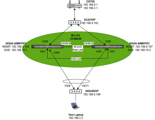
- Two peer switches (e.g. S6500) connected to each other via a peer-link (one or more high-speed ports) and a DAD-link (a separate routed port on each switch).
- One or more downstream switches or devices connecting to BOTH peer switches with LAG (dual-homed access).
- An upstream router/gateway or switch connecting to BOTH peer switches, either via a LAG or individual uplinks.
Control Plane
Because the control planes are independent, a software fault, crash, or reboot on one peer does not affect the other. This is the primary architectural advantage over stacking.
Data Plane
From the perspective of a connected downstream device, the two peer switches appear as a single logical switch. The LAG formed between the downstream device and the M-LAG domain uses standard LACP and distributes traffic across member links on both peers simultaneously.
Deployment Scenarios
Layer 2 Only
In this model, the M-LAG peer switches perform only Layer 2 forwarding. All routing (IP forwarding) is handled by an upstream gateway or router. The M-LAG system is responsible exclusively for frame switching between the access layer and the upstream router.
Typical Use Case
A network where a router handles inter-VLAN routing, and M-LAG switches are deployed at the aggregation layer to provide link and device redundancy for access switches and wireless APs.
Layer 3 Forwarding
In this model, the M-LAG peer switches are also responsible for routing between VLANs. This is relevant when the M-LAG system must act as the default gateway for devices in the access layer, eliminating the need for a separate upstream router to handle inter-VLAN traffic.
Both M-LAG peer switches must have Layer 3 interfaces configured in all VLANs with the same IP addresses, effectively acting as one logical gateway (similar to VRRP in behaviour).
Typical Use Case
A campus network where the aggregation switches need to route traffic between the access VLAN (e.g., VLAN 2, used by PCs and APs) and the uplink VLAN (e.g., VLAN 3, connecting to the core router). The M-LAG pair acts as the Layer 3 gateway for all access-layer devices.
Configuration
This section explains the configuration sequence and the reasoning behind each step, using the Layer 2 scenario as the primary reference.
The full configuration commands are provided on Section 7.
Warning
Do NOT connect all cables before completing the LAG, peer-link, and DAD-link configuration. Connecting cables to unconfigured ports, especially those that will eventually become LAG members, can cause switching loops and network instability.
Step 1 — Power Up Devices Without Data Cables
Start by powering all switches and connecting only the out-of-band management cables (console access). This allows you to complete all configuration before any data traffic flows. The peer-link, DAD-link, and all LAGs should be configured first; data cables for those interfaces are connected only after configuration is complete.
Step 2 — Assign Management IP Addresses
Assign a static (or DHCP-allocated) IP address to the management VLAN interface (VLAN 1) on every switch in the topology. This ensures that each device is individually reachable for management purposes, even after M-LAG is active.
Example for Switch 1 (S6500-24GP4XF):
|
interface vlan 1 ip address 192.168.0.104 255.255.255.0 exit |
Repeat for each switch, assigning a unique IP address in the same management subnet.
Step 3 — Create and Assign Service VLANs
Create the required service VLANs (VLAN2 was used here for testing) on all switches and configure trunk/access membership on the relevant ports:
- Trunk ports (connecting between switches and to the router): tag the service VLAN(s).
- Access ports (connecting to endpoint devices such as PCs and APs): set the service VLAN as the untagged VLAN and remove VLAN 1.
Do not configure VLAN membership on ports that will become LAG members yet, as those will be configured when the LAGs are created in Step 6.
Step 4 — Enable M-LAG and Configure the Peer-Link
On each peer switch, enable M-LAG and specify the same Domain ID. Then designate the high-speed uplink ports as peer-link interfaces. The port speed of the peer-link interfaces must match the highest-speed uplinks available on those switches (e.g., if the fastest uplinks are 10G, the peer-link must use 10G ports — a 1G cable is not acceptable here).
You can designate multiple ports as peer-link ports to provide redundancy on the peer-link itself.
|
! On both peer switches (same Domain ID required): mlag enable 1 mlag domain 1
! Designate peer-link ports (e.g., ports 49 and 50): interface 1/0/49-50 ! (peer-link is activated by the mlag domain config above)
|
Step 5 — Configure the DAD-Link
Assign the DAD-link port on each switch as a routed (Layer 3) interface and specify the source and peer IP addresses. These IP addresses are used solely for DAD probe packets — they do not need to be part of any service VLAN or management subnet. A dedicated /30 subnet is a common choice.
|
! On Switch 1: dad interface 1/0/1 dad param peer-ip-address 192.168.10.2 src-ip-address 192.168.10.1 dad enable exit
! On Switch 2: dad interface 1/0/1 dad param peer-ip-address 192.168.10.1 src-ip-address 192.168.10.2 dad enable exit |
After completing Steps 4 and 5, the physical peer-link and DAD-link cables can be connected.
Step 6 — Create LAGs and Configure M-LAG Member Ports
Create all the necessary Link Aggregation Groups (LAGs). M-LAG distributes a single logical LAG across both peer switches: the portion of the LAG on Switch 1 and the portion on Switch 2 share the same LAG ID, allowing them to collectively service a single downstream device.
The command to register a LAG as an M-LAG member port is the 'mlag' command applied to the port-channel interface. Without this, the LAG is a standard local LAG and does not participate in the M-LAG domain.
|
! Example — Switch 1, LAG 1 connecting downward to an access switch: interface gigabitEthernet 1/0/5 channel-group 1 mode active exit interface port-channel 1 switchport general allowed vlan 2 tagged mlag ! Registers this LAG as an M-LAG member exit |
Repeat the equivalent configuration on Switch 2 for the same LAG ID, then connect all remaining data cables according to the topology.
Layer 3 Scenario Note: In the Layer 3 scenario, you must configure VLAN interfaces with IP addresses on both peers before enabling M-LAG. The IP address for each interface must be identical on both switches to present a single logical gateway.
Best Practices and Key Considerations
Manual Configuration Consistency
Unlike a stacking system, M-LAG does not propagate configuration changes from one peer to the other. Any M-LAG-relevant configuration change must be applied to both switches manually. If the configurations diverge, the system will generate warning messages.
The following settings must be kept identical on both peers:
- M-LAG domain ID
- Peer-link interface designations
- LAG IDs, LACP modes, and port assignments for M-LAG member ports
- VLAN membership and tagging on all M-LAG-facing interfaces
- Global and per-port IGMP Snooping configuration
- Any redundancy protocol settings relevant to the M-LAG domain
Tip: Use the 'show mlag config-consistency-check' command to identify any configuration mismatches between peers. Run this command after every change to confirm parity.
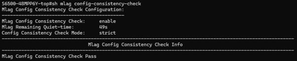
Configuration Consistency Check Modes
Omada switches support two modes for the configuration consistency check:
- Strict Mode: If a configuration mismatch is detected in a key M-LAG parameter, the system automatically shuts down the M-LAG member ports. This prevents unpredictable forwarding behavior but will result in traffic disruption until the inconsistency is resolved.
- Loose Mode: Mismatches generate warning messages in the console/log, but M-LAG member ports remain operational. This is less disruptive but relies on the administrator to proactively notice and resolve the inconsistency.
Choose the appropriate mode based on your environment's tolerance for false positives versus undetected mismatches.
Please note that the command “mlag config-consistency-check mode strict/loose” sets the M-LAG configuration consistency check mode as “strict” or “loose”. If the mode is set to strict, after detecting inconsistencies in key M-LAG configurations, the M-LAG member ports will be automatically shut down to prevent chaos during forwarding. If the mode is set to loose, only warnings will be printed, and the M-LAG member ports will remain up.
Failure Scenarios
Single Link Failure Within a LAG
If one physical cable within a LAG bundle fails, LACP removes that link from the bundle and traffic redistributes across the remaining links. This is handled transparently with no more than a brief recovery interval (typically sub-second). No manual intervention is required.
Peer-Link Failure (Split-Brain)
If the peer-link fails while both switches remain connected to the network, both devices temporarily lose synchronization. DAD immediately begins probing via the DAD-link. If both peers are reachable, the system shuts down M-LAG member ports on one peer (the one with lower priority, or as configured) to ensure only one device continues forwarding. Traffic is disrupted on the affected peer, but the other peer continues forwarding normally, limiting the impact.
If the DAD-link is also down (i.e., both the peer-link and DAD-link have failed), the system enters an unprotected split-brain state.
DAD-Link Failure Only
A DAD-link failure on its own does not affect forwarding, as the peer-link remains operational for synchronization. However, the absence of a functioning DAD-link means that if the peer-link also fails subsequently, the system will not be able to prevent split-brain.
Single Peer Switch Failure
If one peer switch fails or is powered off, all traffic on that switch's M-LAG member ports shifts to the surviving peer. Connected dual-homed devices continue to function through their remaining link to the active peer.
The impact is limited to those devices connected only as orphan ports on the failed switch and those devices will lose connectivity until the switch is restored.
Configuration Examples
The following commands should be replaced with the correct and corresponding of each device in your specific deployment.
The following structure and commands represent the switch configuration sequence for completing Section 5.
Layer 2 Forwarding Scenario
Switch 1 — S6500-24GP4XF
|
interface vlan 1
vlan 2
mlag enable 1 mlag domain 1 interface 1/0/49-50 dad interface 1/0/1 dad param peer-ip-address 192.168.10.2 src-ip-address 192.168.10.1 dad enable exit
interface gigabitEthernet 1/0/5 |
Switch 2 — S6500-24G4XF
|
interface vlan 1
vlan 2
mlag enable 1 mlag domain 1 interface 1/0/49-50 dad interface 1/0/1 dad param peer-ip-address 192.168.10.1 src-ip-address 192.168.10.2 dad enable exit
interface gigabitEthernet 1/0/5 |
Downstream Access Switch — SG6654
|
interface vlan 1
vlan 2
! Access port for test laptop on VLAN2 interface gigabitEthernet 1/0/32 switchport general allowed vlan 2 untagged no switchport general allowed vlan 1 switchport pvid 2
interface range gigabitEthernet 1/0/9,1/0/11 channel-group 1 mode passive exit interface port-channel 1 |
Verification Commands
After completing configuration, use the following commands to verify the M-LAG system is operating correctly:
|
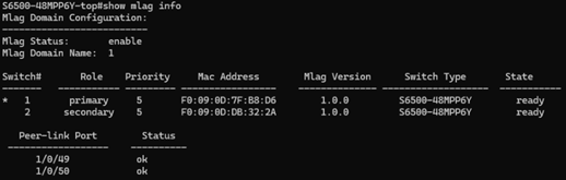
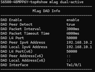
show mlag info ! Overall M-LAG session status and peer-link state show mlag members-info ! Status of all M-LAG member ports show mlag dual-active ! DAD status and current active/standby role show mlag config-consistency-check ! Identify configuration mismatches between peers |
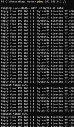
Tip: Perform an extended ping from a PC to the upstream gateway, then simulate failure scenarios one at a time (remove a single LAG cable, unplug the peer-link, then unplug the DAD-link, then shut down one peer, etc.).
Acceptable behaviour is no more than 1-2 packets dropped during each individual failover event.
Omada Controller Deployment Note
The configuration examples in this document were produced using direct console (CLI) access to each switch. This is the most straightforward method for initial lab testing and for building familiarity with the command structure.
In production environments managed through the Omada Controller, the same configuration can be deployed at scale using the Omada Controller's CLI Template feature. CLI templates allow an administrator to define a block of CLI commands once and push that configuration to multiple devices simultaneously.
Recommended Approach for M-LAG via Omada Controller
- Build and validate the full configuration manually on a lab pair of switches using the console, following the steps in this document.
- Once verified, encode the configuration as a CLI template within the Omada Controller.
- Use the template feature to deploy the configuration to production peer devices, ensuring that switch-specific variables (IP addresses, port numbers, DAD peer/source IPs) are parameterised correctly per device.
- Run the consistency check command remotely via the controller after deployment to confirm both peers are aligned.
Note: Even when using the Omada Controller for deployment, M-LAG configuration is not synchronized automatically between peers by the controller. The template must include the correct configuration for each individual switch. Apply the peer-specific version of the template to each device separately.
Quick Reference: Key Commands
|
Command |
Purpose |
|
mlag enable <domain-id> |
Enable M-LAG and set the domain ID on a peer switch |
|
mlag domain <id> |
Enter M-LAG domain configuration mode |
|
interface <port-range> |
Select peer-link ports (within mlag domain context) |
|
dad interface <port> |
Designate the DAD-link port |
|
dad param peer-ip-address <ip> src-ip-address <ip> |
Set DAD peer and source IP addresses |
|
dad enable |
Activate DAD on the configured DAD-link |
|
channel-group <id> mode active/passive |
Assign a physical port to a LAG with LACP |
|
mlag |
Register a port-channel as an M-LAG member port |
|
show mlag info |
Display M-LAG session status and peer-link state |
|
show mlag members-info |
Display M-LAG member port status |
|
show mlag dual-active |
Display DAD status |
|
show mlag config-consistency-check |
Check for configuration mismatches between peers |
|
mlag config-consistency-check mode strict/loose |
Set the consistency check enforcement mode |