Official How to Design and Deploy Your Network with Omada Design Hub

How to Design and Deploy Your Network with Omada Design Hub
The Omada Design Hub offers a convenient, visual platform for planning your network and selecting the most suitable network products to deploy. Its built-in AI tools help facilitate your planning process. You can find more information on the features here.
This step-by-step guide will walk you through designing a two-story office network to help you explore the platform and understand its features.
1. Access Omada Design Hub
To access Omada Design Hub, visit https://design.tplinkcloud.com/. You will need a TP-Link ID to sign in. If you do not have an account, create one first.
2. Create a New Project
After logging in, follow these steps to create a new project:
1) Click +Add in the Project List page.
2) Specify a project name and select an appropriate scenario, such as “Office Network” as the project name and “Office” as the scenario. Click Confirm.
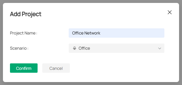
If the predefined scenarios do not meet your needs, click + Add New Scenario to create your own.
3. Create a New Floor
After creating your project, you will be automatically redirected to the following Floor Plan page. Follow these steps to create a new floor:
1) Click Upload Floor Plan. Multiple formats are supported, but only one file can be uploaded at a time.
2) Specify the floor name, floor number, and ceiling height. Select a layout that best suits your map to increase the accuracy of the simulation. Click Confirm.
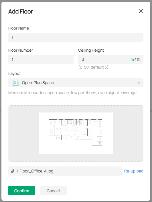
You can switch between meters and feet when setting the ceiling height. You can also click the image to preview it and re-upload another file if you want to change it.
3) After uploading the floor plan, you will need to set your floor plan scale. Left-click at a starting point to draw a line on the map and left-click again to finish drawing. Specify its length. Click Apply.
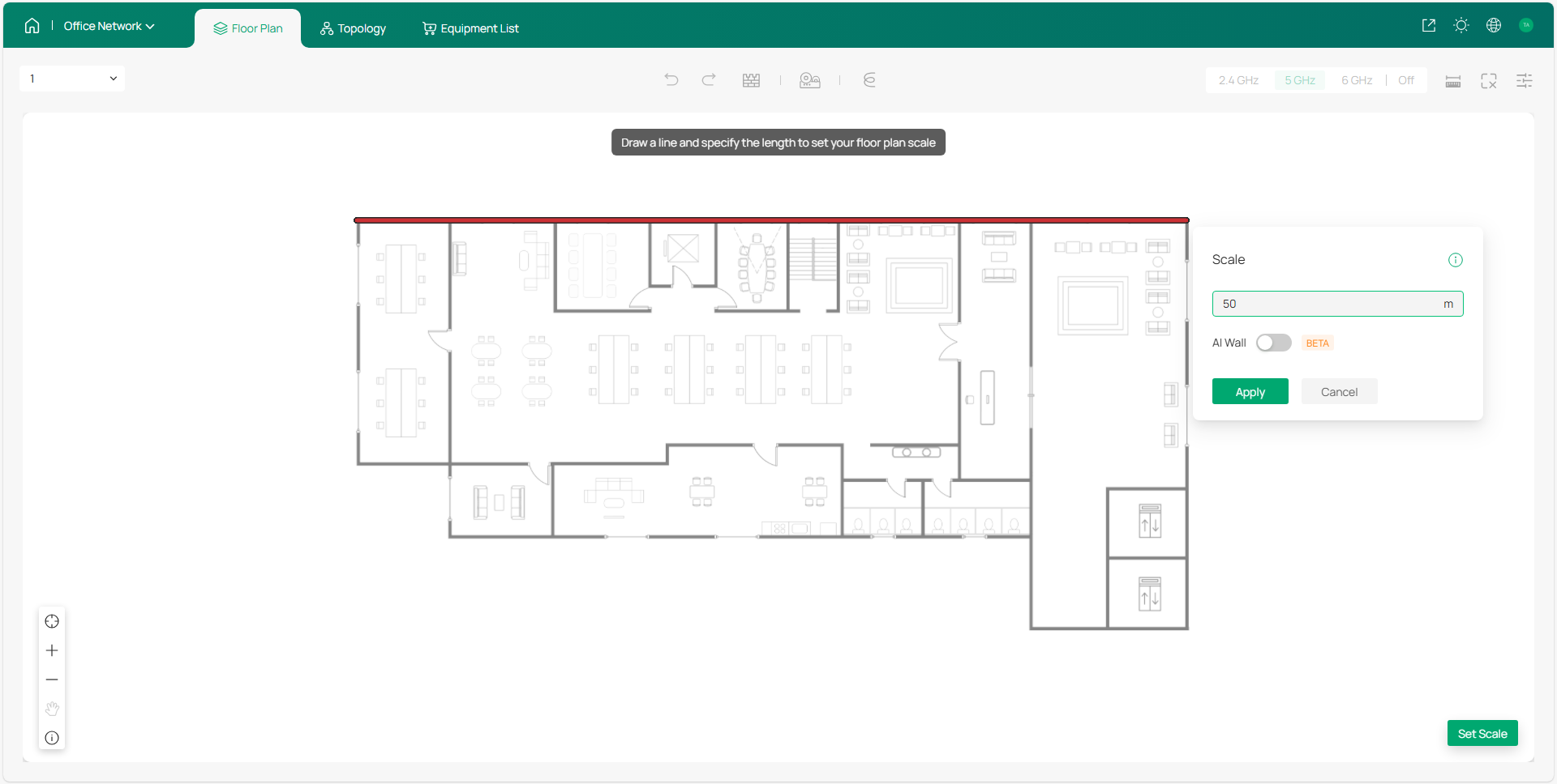
Make sure the floor plan scale reflects the actual environment, as it impacts wall simulation, cable length, and wireless coverage.
To reset the scale, click the scale icon in the bottom right.
4. Draw Walls
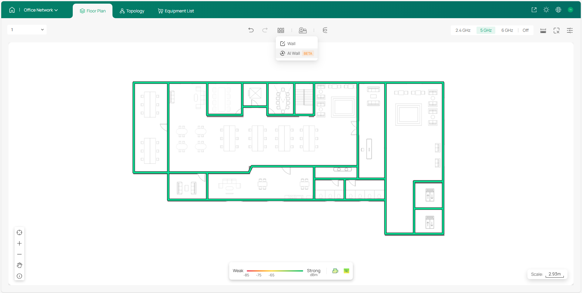
Before deploying devices, please set the walls of your floor plan. You can either draw the walls manually or use the AI Wall feature to detect the walls of your floor plan automatically.
If drawing the walls manually, you can add new walls, move, split, or delete the existing walls, and change the wall materials to match your physical space.
If using the AI Wall feature, your floor plan walls will be automatically detected and set. You will still need to manually set the material of each wall.
5. Deploy Devices
With your layout ready, you can start deploying devices. You can either set your devices manually or use the AI Devices tool to place devices automatically.
1) Click AI Devices and select an AP model. Click Apply.
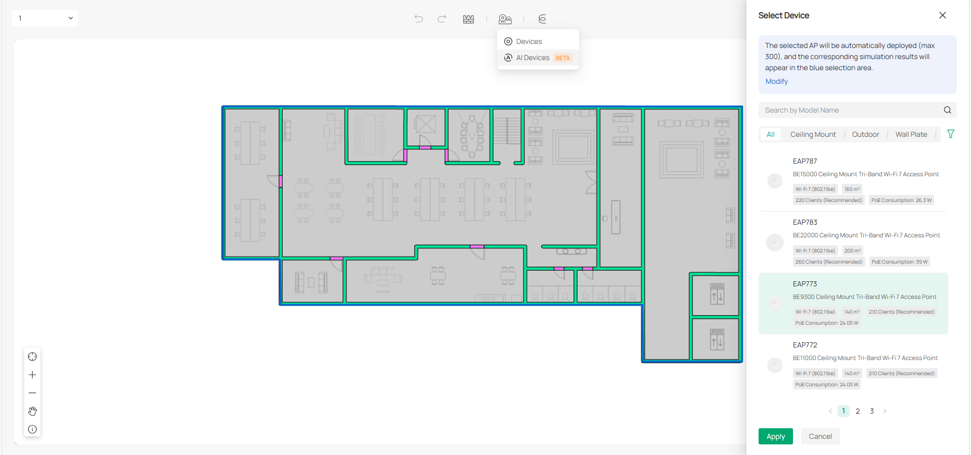
Note: Only EAPs are currently available for the AI Devices feature.
2) Click a specific band to view the Wi-Fi coverage and adjust the AP deployment.
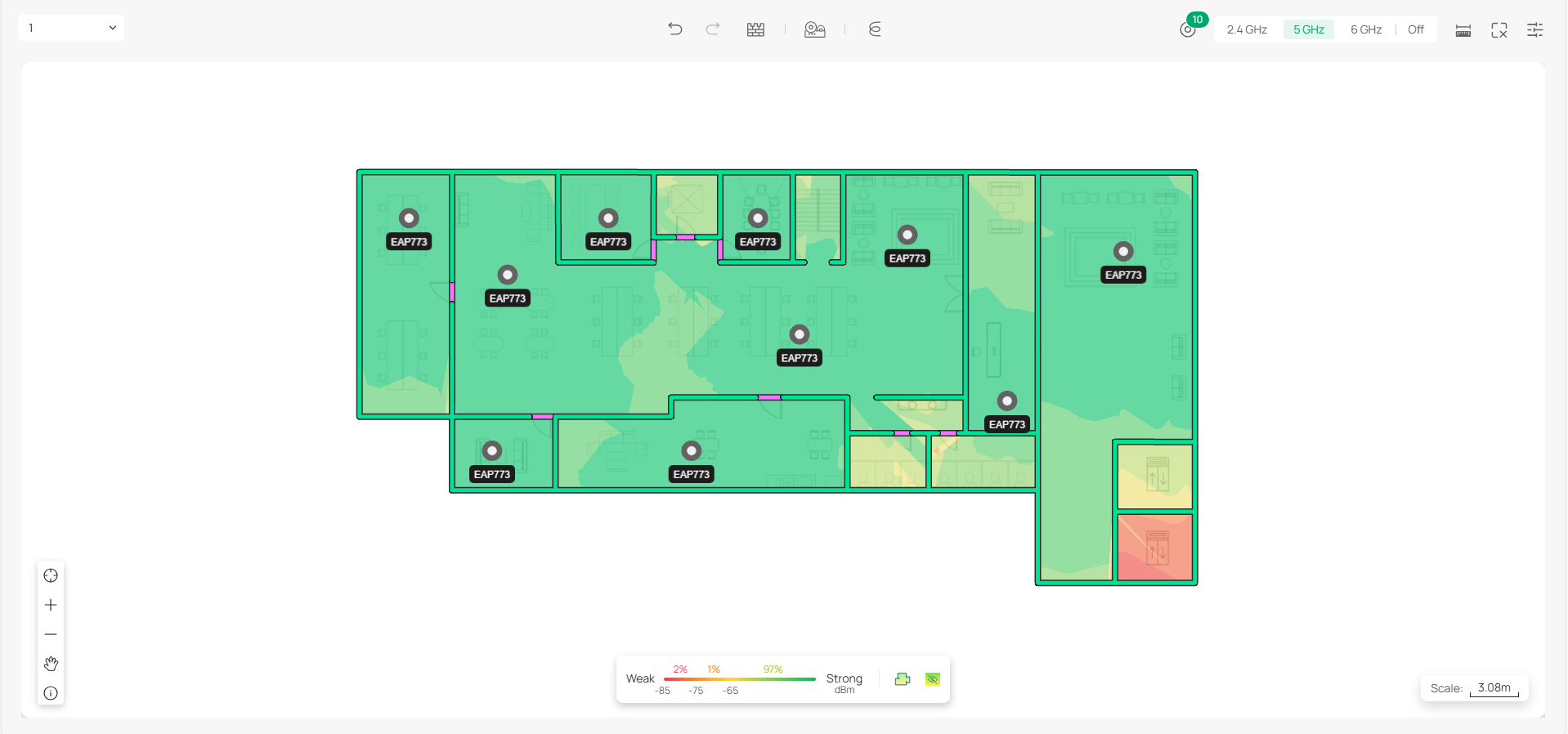
Hover your mouse over an AP, and the Wi-Fi coverage will also be visualized in the heat map.
3) Add gateways, switches or extra APs manually based on your actual need. Click Devices and select a model. Place the device to a desired location.
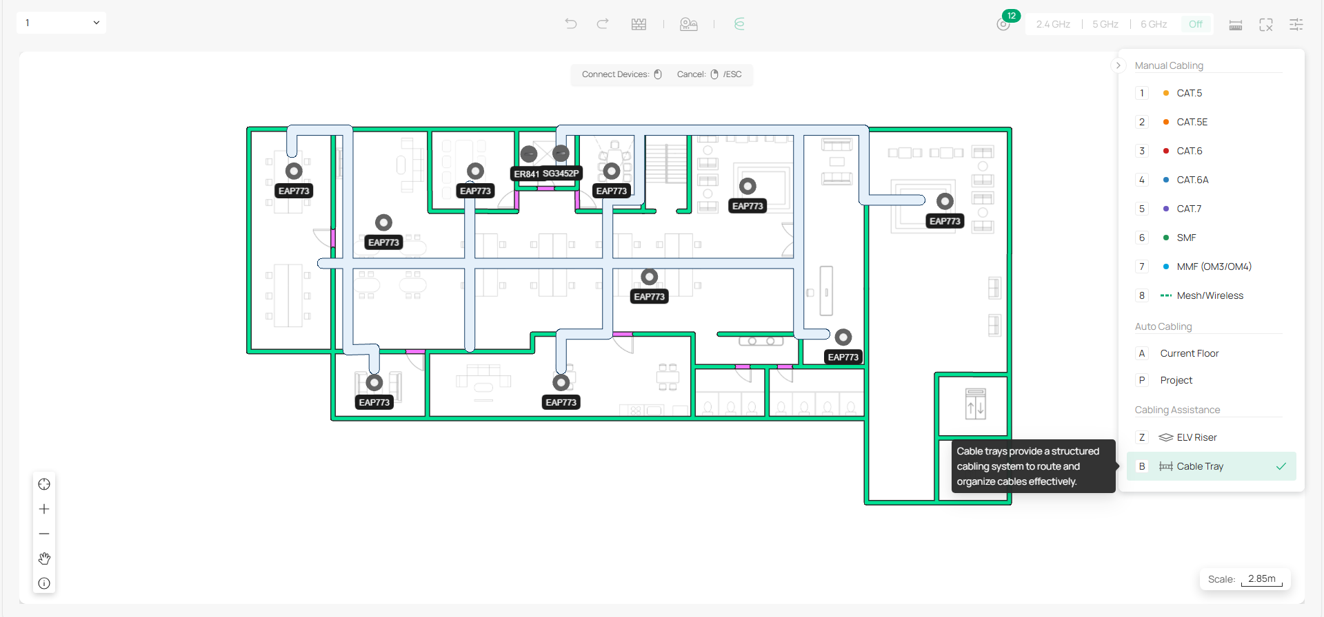
6. Deploy Cables
After devices are deployed, you can now route cabling to each device. This section describes how to deploy cables for both single and multi-floor networks.
Deploying Cables for a Single Floor
Click Cable to open the Cable Tray. From here, you can manually set up the cables or use the Auto Cabling feature to quickly deploy cables to each device.
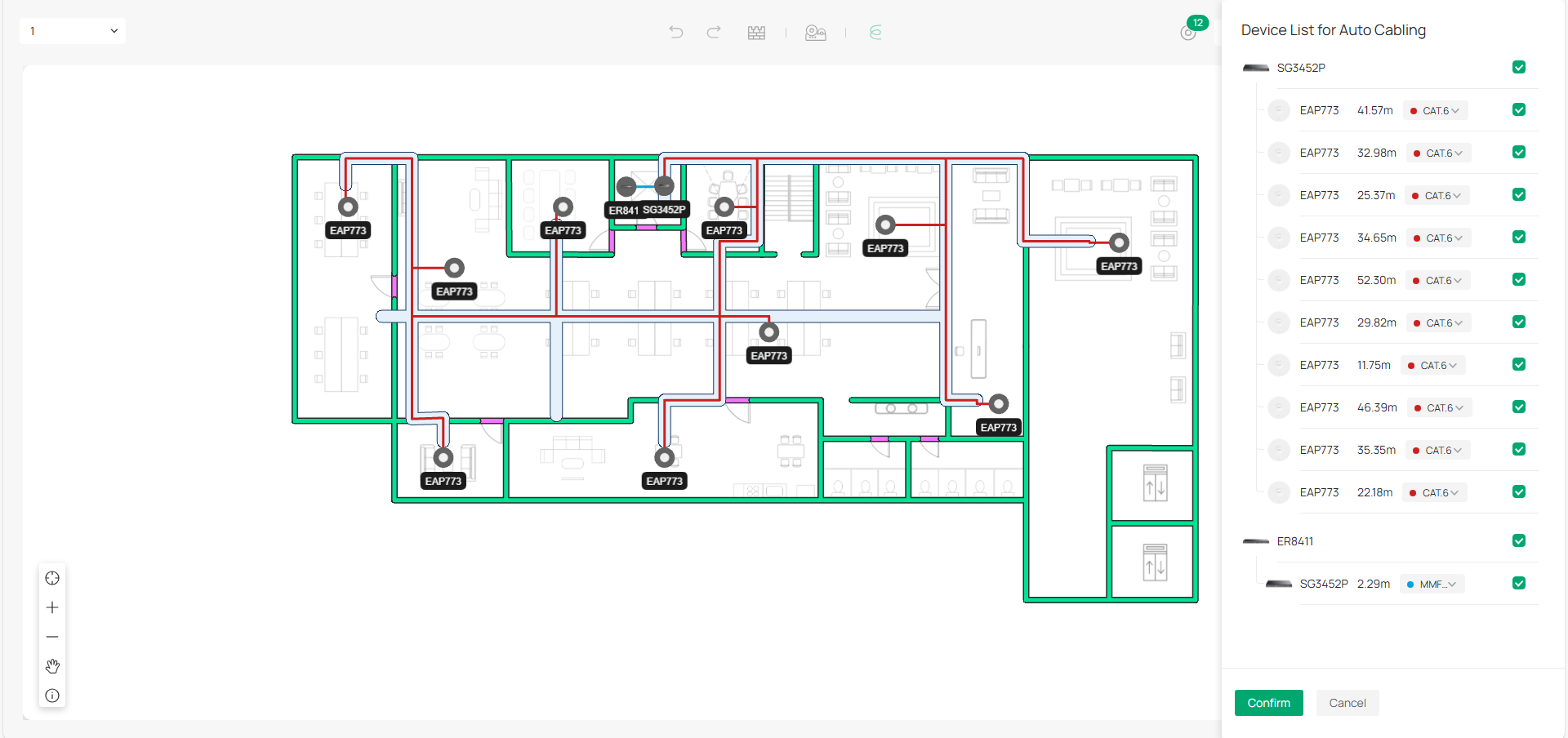
For this example, we’ll use the Auto Cabling feature to deploy cables to the devices. Once Auto Cabling completes, modify the cabling result to meet your physical needs, then click Confirm.
Deploying Cables Across Multiple Floors
Auto Cabling also supports multi-floor cabling within a project.
1) Follow the same procedure above to create the second floor.
2) Deploy an ELV riser on each floor and select the ELV riser type for the floor.
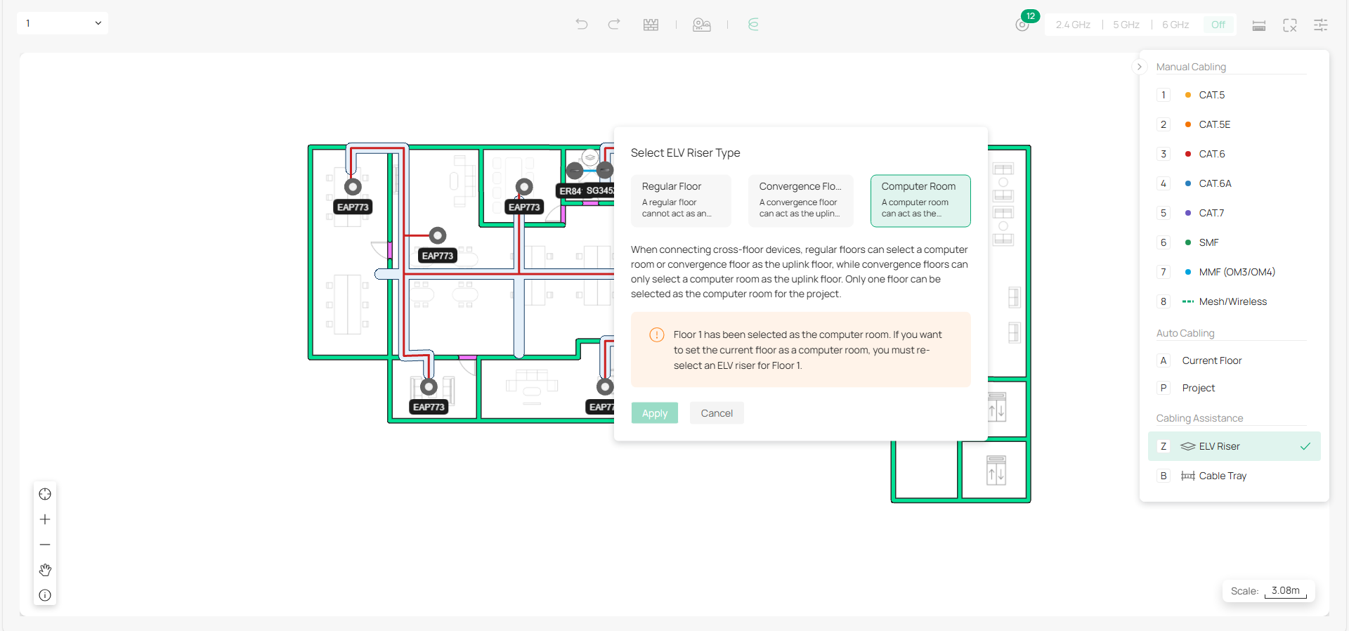
Note: Cross-floor devices need to be connected through ELV risers.
3) Use Auto Cabling for the project and adjust the cables.
7. View Topology
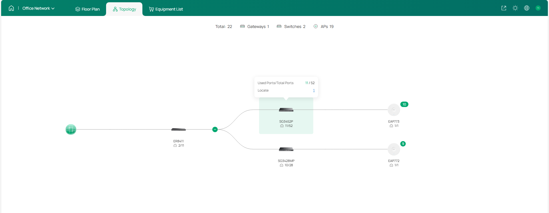
Click Topology on the top to view the network topology of the whole project. You can hover your mouse over a specific device to check its port usage and locate the device.
8. Check Equipment List and Fees
Go to Equipment List to check the devices deployed and the accessories. You can specify the quantity and unit price to calculate the total cost of your deployment.
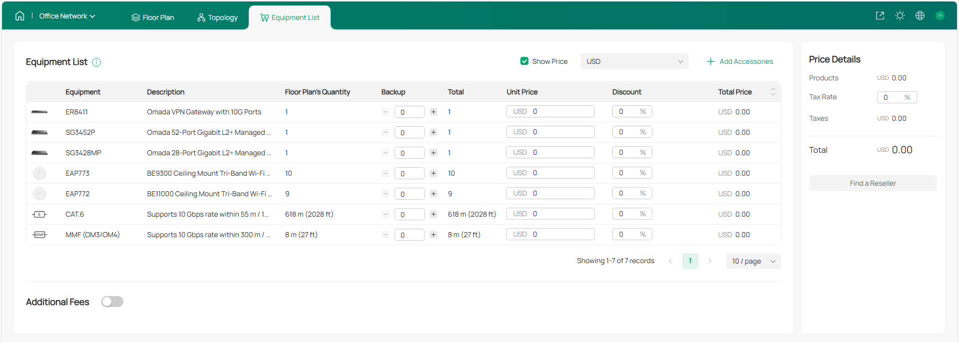
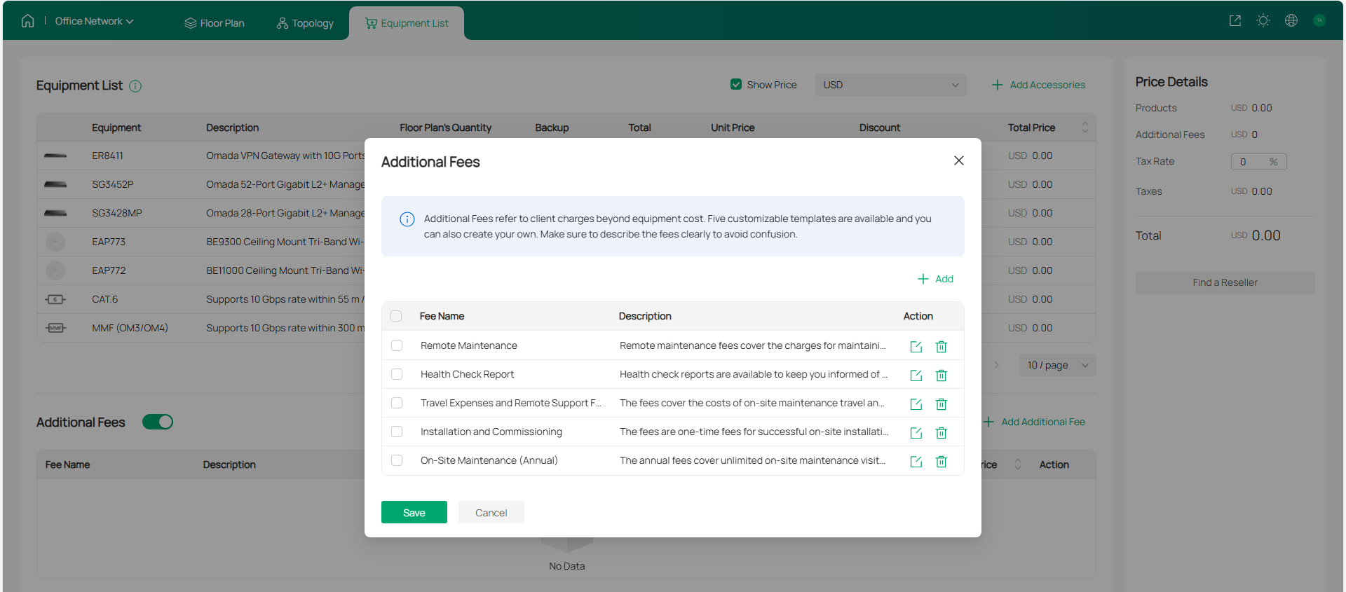
You can also add additional fees according to your needs.
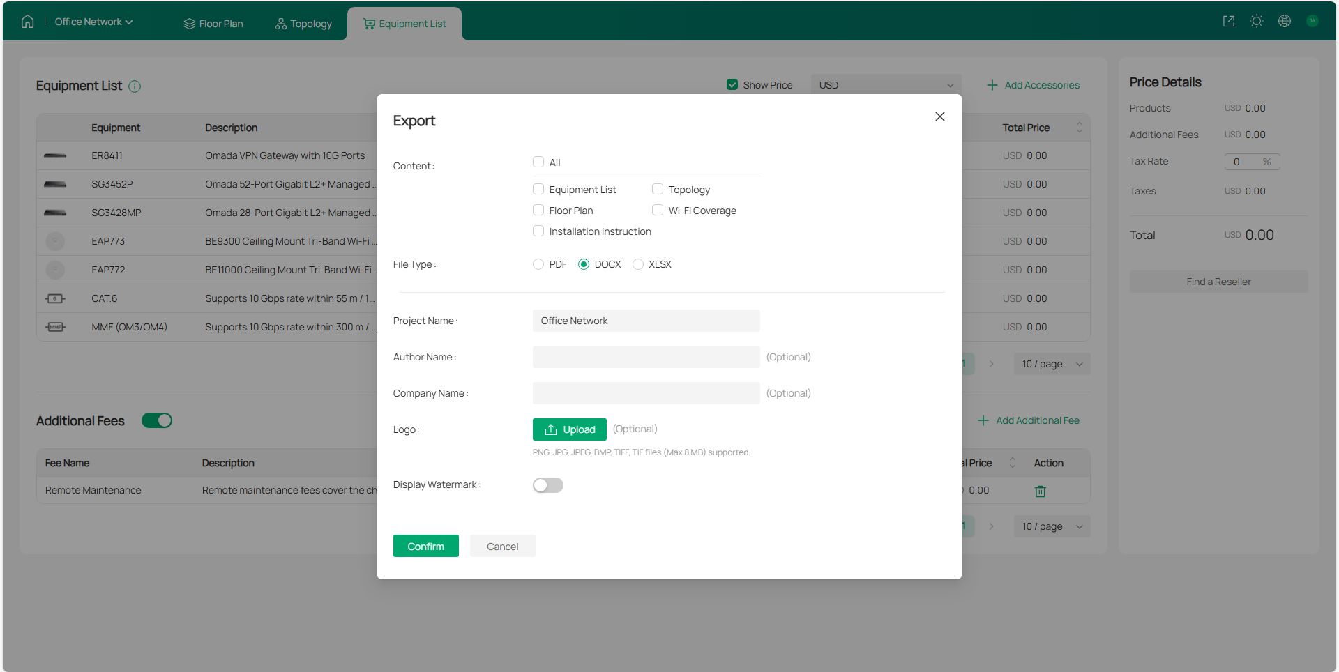
9. Export Network Design Report
Once you are satisfied with your network plan, you can export a report for reference during the actual network deployment.
For detailed guidance and more information, refer to the Omada Design Hub user guide.