Configuration Guide How to Configure Hotel Multicast IPTV via Omada Switch and Omada Controller (based on version 6.0)

Multicast is one of the key technologies used in hotel IPTV services. Any Omada SG2xxx series and above support a full set of multicast features, including IGMP Snooping, IGMP Querier, Drop Unknown Multicast, and Fast Leave. These capabilities enable the switches to deliver a stable multicast IPTV service for hotels of any scale.
Since Omada Controller version 6.0, the configuration of multicast IPTV has become even easier through an intuitive GUI. It offers scenario-oriented settings tailored for hotel IPTV applications, making IPTV deployment simple and user-friendly.
With the Omada SDN network, you can also benefit from centralized management, remote management by cloud access, and Zero-Touch Provisioning (ZTP), delivering additional value to IPTV integrators, IT system integrators, and managed service providers (MSP).
In this guide, we will demonstrate the best practice configuration for hotel multicast IPTV using the Omada Controller.
1. Prerequisites
- Omada Controller version 6.0.
- Omada SG2xxx series and above level switches, and with latest firmware (adapted to the Omada Controller C6.0)
- The multicast sources and TVs are located in the same VLAN. If the multicast sources and TVs are not on the same Layer 2 network, Layer 3 multicast routing protocols such as PIM-SM will be required, which is beyond the scope of this guide.
2. Background Knowledge
To better understand the configurations, we will provide some simple background explanations.
If you are already familiar with these concepts, please skip this section.
2.1 IGMP Snooping
Without IGMP Snooping, multicast traffic is transmitted through the switch like broadcast traffic, which increases bandwidth usage and degrades network performance. IGMP Snooping helps generate a multicast forwarding table using IGMP report and querier packets, ensuring that multicast packets are only sent to the intended ports.
2.2 IGMP Querier
Without an IGMP Querier, the multicast forwarding table can age out. The IGMP Querier periodically sends IGMP Querier packets, allowing the switch to maintain the multicast forwarding table. It is important to note that there must be exactly one IGMP Querier in the multicast network.
2.3 Drop-unknown multicast
It is highly recommended to enable this feature because most IPTV streamers indiscriminately send traffic for all channels. If the Drop-Unknown Multicast feature is not enabled, the network can become saturated with unnecessary multicast traffic, negatively impacting overall IPTV performance. When Drop-Unknown Multicast is enabled, the switch first checks whether a multicast forwarding entry exists for the group; if not, the switch drops the multicast traffic.
2.4 Multicast Fast Leave
When the switch receives an IGMP Leave packet from a port, by default it does not immediately remove the port from the multicast forwarding table. Instead, the port is removed after the aging time expires. With the Fast Leave feature enabled, the switch removes the port from the multicast forwarding table as soon as it receives the IGMP Leave packet. Fast Leave ensures faster and smoother channel switching and reduces unnecessary multicast traffic on the network. It is recommended to enable this feature for hotel IPTV deployments.
Fast Leave should only be enabled on ports with a single TV/STB connected. Do not enable it on ports cascaded with other switches or APs, because enabling it in such scenarios may cause channel switching on one TV to freeze the video on another TV connected to the same switch/AP behind that port.
Taking the following topology as an example:
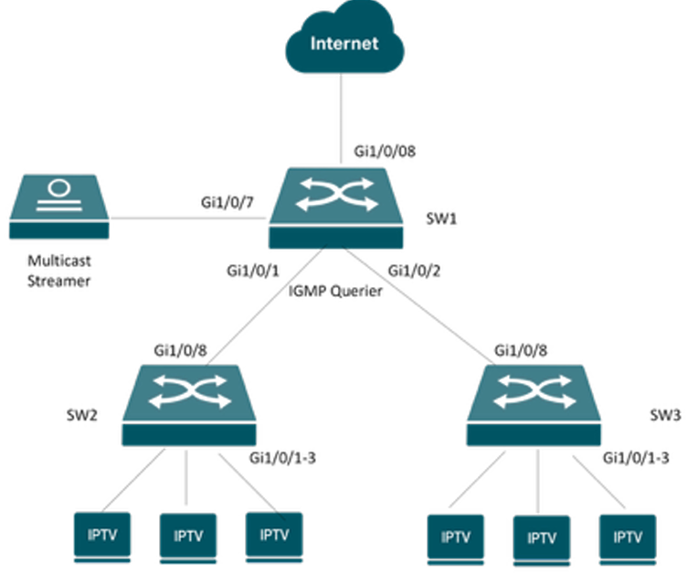
For SW1, you should not enable Fast Leave on the downlink ports, because these ports are connected to other switches where multiple STBs are connected. For example, if Fast Leave is enabled on port Gi1/0/1, when this port receives an IGMP Leave packet from the downlinks, SW1 will immediately remove the port from the multicast forwarding table. This may cause channel freezing issues for other STBs on the downlink that are watching the same channel.
2.5 Report Suppression (Optional)
When the switch receives multiple IGMP Report packets from multiple STBs requesting to join the same source group within an IGMP Querier interval, the switch forwards only the first report packet to the upstream network. This reduces unnecessary report traffic on the network. It is recommended to enable this feature on all switches, especially in large IPTV deployments.
2.6 IGMP Router Port (Optional)
The router port is the port through which multicast traffic is forwarded and to which IGMP Report/Leave packets are sent to on a switch. The switch can automatically select the router port based on where it receives IGMP Report packets or PIM Hello packets. In most cases, you do not need to configure the router port manually and can rely on the switch’s default settings.
3. Hotel Multicast IPTV Configuration examaple
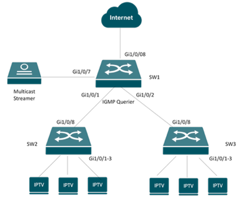
3.1 Network Topology
We will use the following network for demostration. The Multicast Streamer is connected to SW1's Gi1/0/7 port. SW1 works as the IGMP Querier. And its Gi1/0/1 and Gi1/0/2 port connect the access switch SW2 and SW3. SW2 and SW3's Gi1/0/1-3 ports connect the IPTV TV/STBs.
3.2 VLAN Plan
To ensure stable IPTV service, multicast traffic should be placed on a dedicated VLAN. This prevents interference from other network traffic. If you have switches dedicated to IPTV, you can use the default VLAN 1. In this guide, we will use VLAN 90 as the IPTV VLAN, and VLAN 1(default VLAN) as Management VLAN.
3.3 Ports Plan
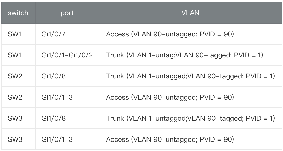
3.5 Configure on the Omada Controller (version 6.0)
- Creat VLAN for IPTV
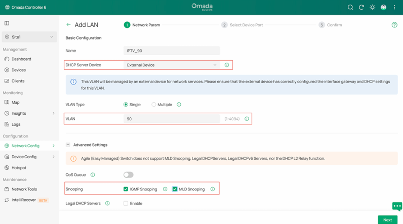
Navigate to Site View → Network Config → Network Settings → LAN → VLAN and create VLAN 90 for IPTV as shown below.
In our case, we will use a third-party device as the DHCP server, so we select External Device for the DHCP Server Device option. MLD Snooping is used for IPv6 multicast, and it can be enabled at the same time even if IPv6 multicast is not being used in this scenario.
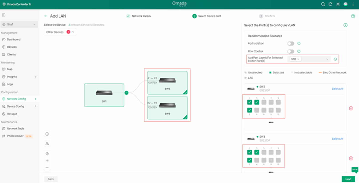
Click Next, and you can select the switches and configure the access ports directly here.
In this example, click SW2 and SW3, then select ports 1~3 on both switches. This will configure ports 1~3 on SW2 and SW3 as Access ports for VLAN 90. You do not need to configure the trunk ports manually — the remaining ports will be set as Trunk ports by default. It is recommended to assign Port Labels to these ports so that you can easily identify or modify them later in batch. You can also skip this step and perform these settings after the VLAN is created.
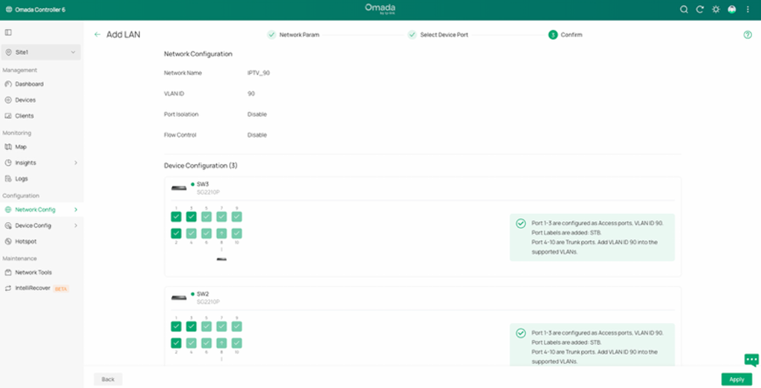
Click Next, it will give a summary of the settings. Click Apply to save.
- Configure the Multicast Features
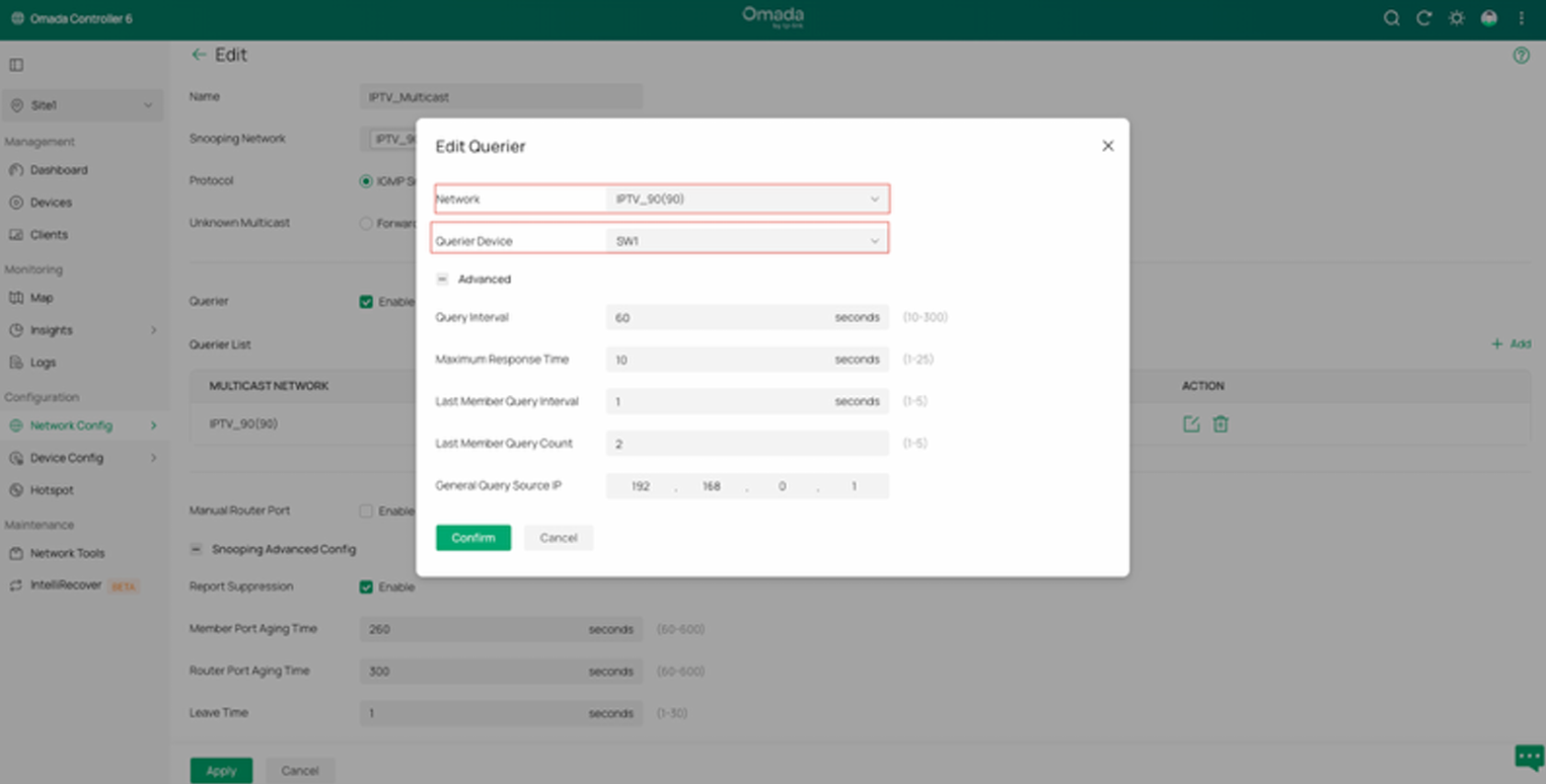
Go to Site View → Network Config → Network Settings → LAN → Multicast Snooping, and click Add to create a new configuration. Select VLAN 90 as the Snooping Network and choose IGMP Snooping (v4) as the Protocol. Enable Drop Unknown Multicast, and enable the Querier on the aggregation switch (SW1 in this case) that is closest to the multicast source. Also, enable Report Suppression. You can keep the other settings as default.
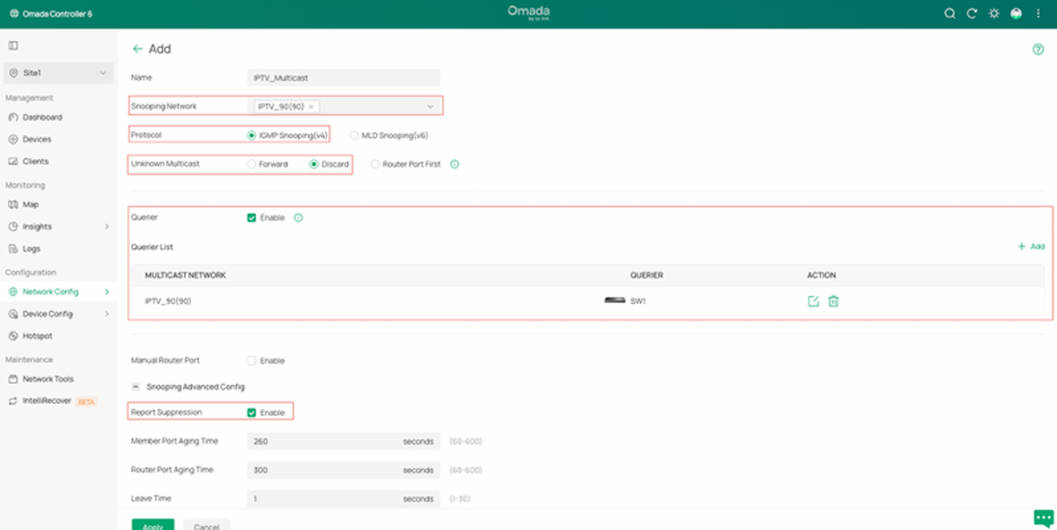
IGMP Querier settings: Select VLAN 90, and choose the switch that will act as the Querier. You can keep the other settings as default.
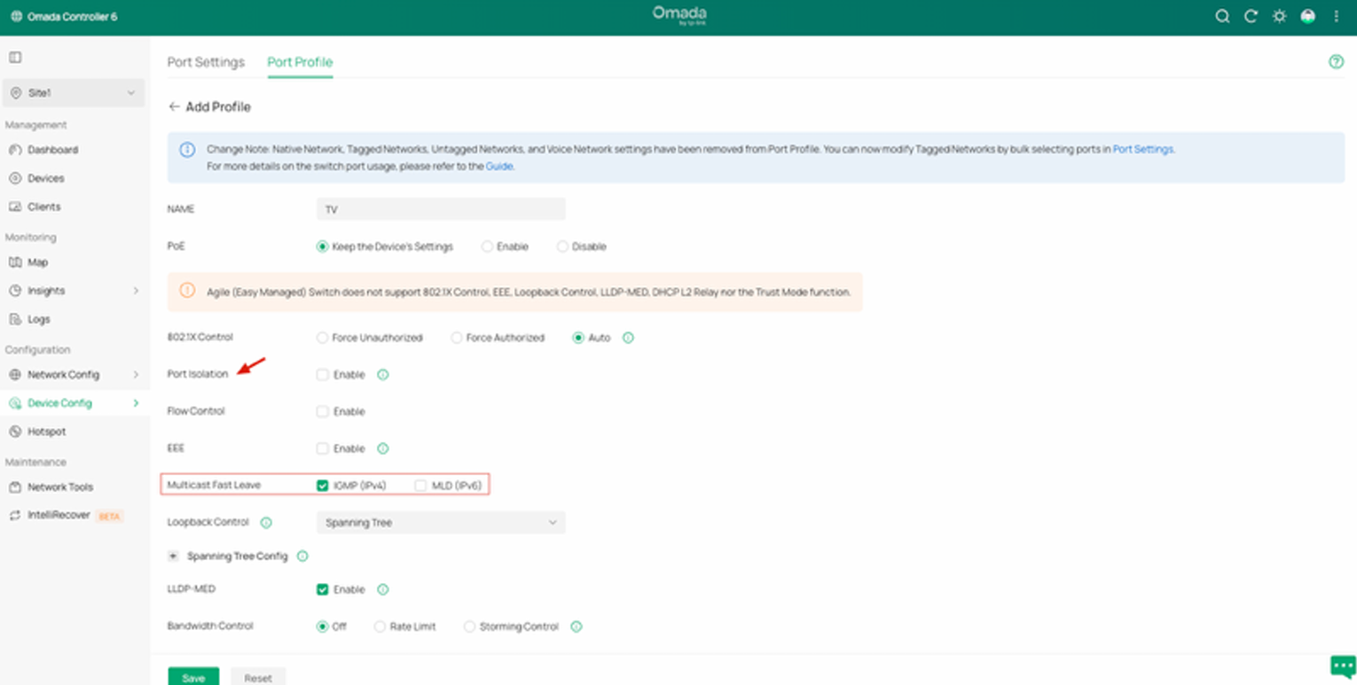
- Create Port Profile with Fast Leave for TV
Navigate to Site View → Device Config → Switch → Switch Ports → Port Profile, and click Add to create a new port profile. Enable Multicast Fast Leave. If you want to isolate the TVs, you can also enable Port Isolation. You can keep the other settings as default.
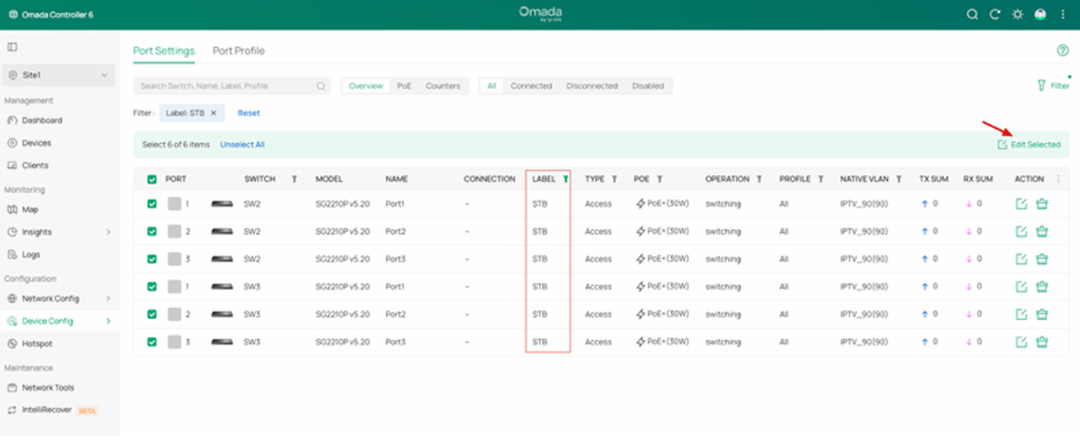
- Apply the TV port profile to the switch port
Go to Site View → Device Config → Switch → Switch Ports → Port Settings. If you have set up port labels, you can filter the ports by label.
Select all the filtered ports, then click Edit Selected in the top-right corner to edit them in batch.
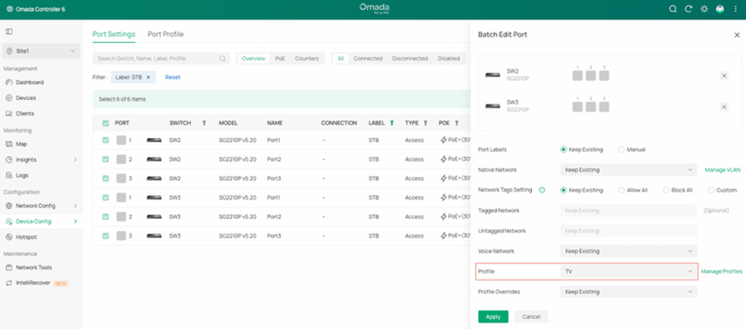
Choose the TV profile you just created, keep the other settings as default, and click Apply to save the changes.
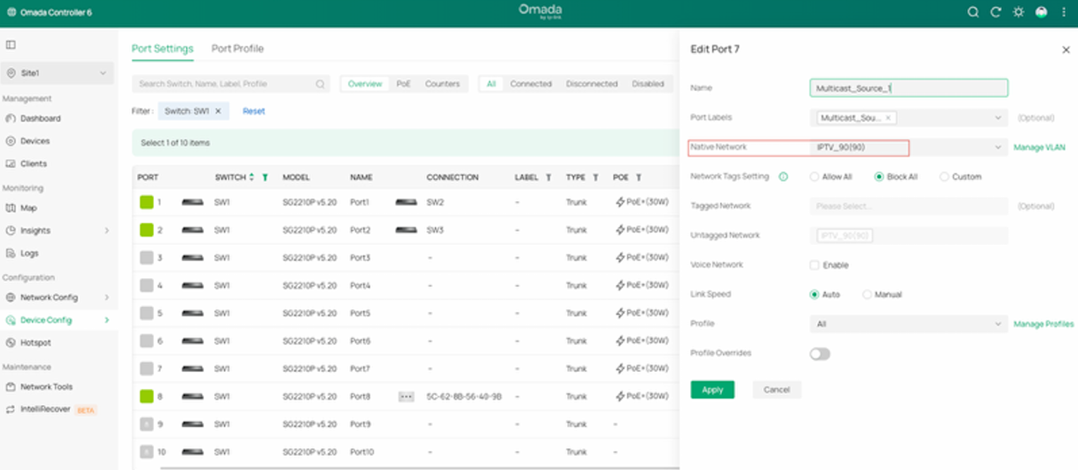
- Configure the port that connect the multicast source
Configure the port’s VLAN settings (tagged or untagged) according to the multicast source server’s requirements.
In this example, we use an Access port on VLAN 90 for the multicast source.
Till now, all configurations for Multicast are complete.
4. Trouleshooting
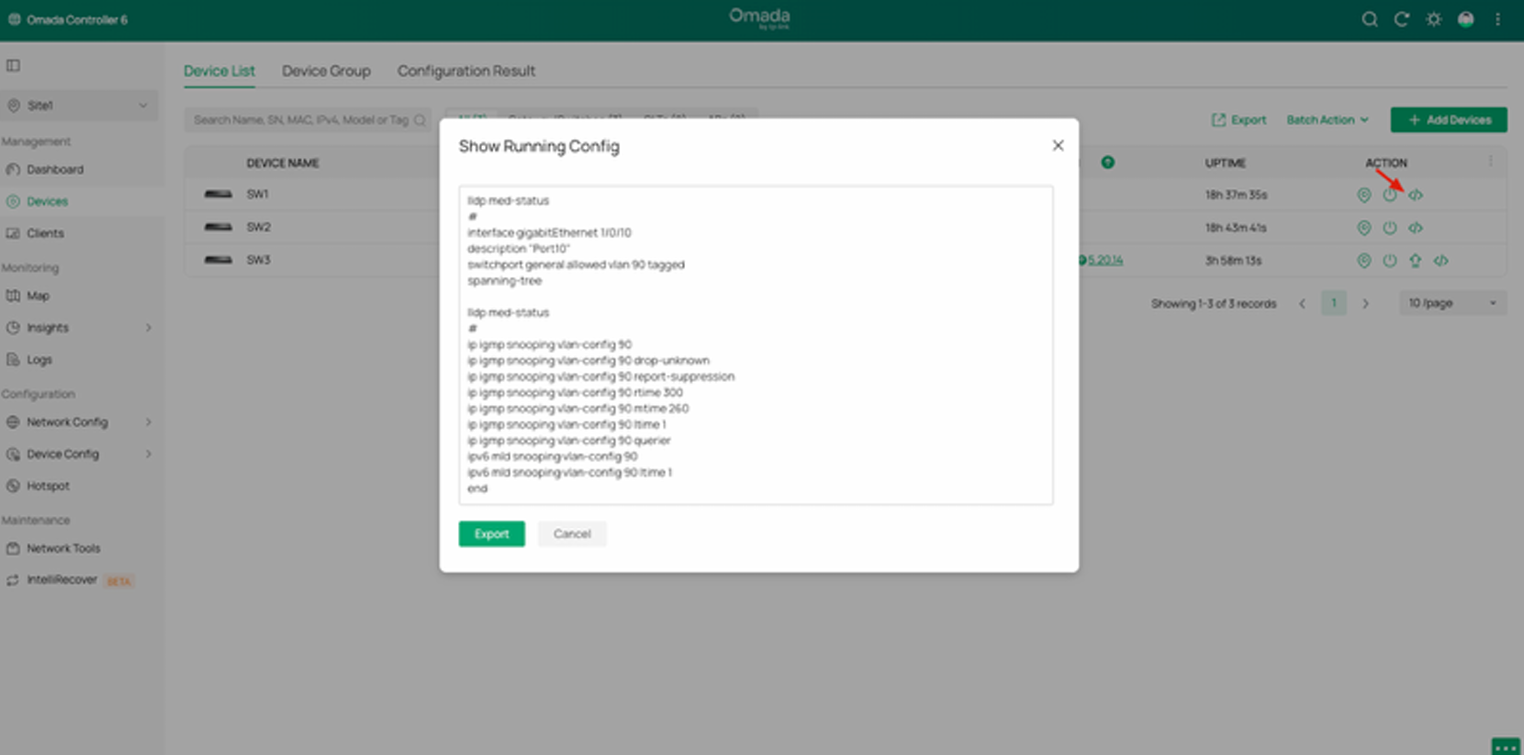
Verify the configuration: By clicking this icon, you can view the running configuration of the switch to verify whether your settings are correct.