ER605
 This thread has been locked for further replies. You can start a new thread to share your ideas or ask questions.
ER605
Hello everyone,
I am currently reaching the limits of my network knowledge, especially with regard to VLAN configuration.
•For a standalone building with an internet connection via an AVM FritzBox LTE, I want to set up the following configuration, but I keep failing. This means that all devices receive IP addresses from the address range 192.168.0.1/24, even though I believe I have configured the LANs, VLANs, associated DHCP servers, and address ranges correctly.
•The WAN port on the ER605 is connected to a network port on the Fritzbox. The internet connection is stable. The administration PC is assigned an IP address from the 192.168.0.1/24 address range. The IP address 192.168.0.1 is specified as the gateway. (ipconfig/all)
•LAN 1
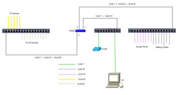
•VLAN 10 (physical LAN port 1 on the ER605) is connected to port 8 of the TL-SG108PE (V5.0). The IP range is set to 192.168.aab.1/24. The TL-OC200 is connected to port 1 of the TL-SG108PE, and the administration PC is connected to port 7.
•LAN 2
•VLAN 20 (physical LAN port 2 on the ER605) is connected to port 16 on the TL-SG1016PE-2 (V6.0). Switch ports 9 - 15 should belong to VLAN 20. These ports supply the components of the photovoltaic system and the heating system. All connected devices should be assigned a fixed IP address from the 192.168.aac.1/24 address range.
•VLAN 30 (physical LAN port 2 on the ER605) is connected to port 16 on the TL-SG1016PE-2. Six EAP653s and one AX1800 (outdoor) are connected to ports 2–8. Both the private network and a guest network should run on the seven APs. All APs should be assigned fixed IP addresses from the 192.168.aad.1/24 address range by the DHCP server.
•LAN 4
•VLAN 40 (physical LAN port 3 on the ER605) is connected to port 1 of the TL-SG1016PE-1. 5 IP cameras are connected to switch ports 2 - 6. The cameras should be assigned fixed IP addresses from the 192.1668.aae.1/24 address range.
•VLAN 50: (physical LAN port 3 on the ER605) is connected to port 1 of the TL-SG1016PE-1. Switch ports 7 - 16 supply the RJ-45 sockets in the house and should be assigned their own IP addresses from the 192.168.aaf.1/24 address range.
•My questions:
•Is this configuration feasible with the existing components?
•How must the LANs and VLANs be configured on the TL-ER605 for this configuration to work?
•How must the VLANs be configured on the switches?
•I know that the switches cannot be configured via the OC200, but that each switch must be configured individually.
•Is it necessary to replace the existing switches with Omada switches in order to get the desired configuration up and running?
Thank you for your help.
Christian