Knowledge Base Guide: Set Up An All TP Link Omada Pseudo-One-Way (Unidirectional) Stateful ACL for your Network
 This thread has been locked for further replies. You can start a new thread to share your ideas or ask questions.
Guide: Set Up An All TP Link Omada Pseudo-Perimeter Network, with Pseudo-One-Way (Unidirectional) Stateful ACL for Secured IoT Network and Home Computing without explicit ACL definition
Short Version Videos:
- Part1 - https://youtu.be/VTrg2ecGetA
- Part 2 - https://youtu.be/gQW0kvN_too
Hardware Used for this Guide:
- 1x OC-200
- 1x ER-7206 (SDN Router A)
- 1x ER-605
- 2x SG-2210P
Optional Hardware:
- 2x EAP-610
Alternative Hardware/Software Requirement:
- 2x ER-605 Gateway or 2x ER-7206
- TP Link Omada Controller (Hardware, Software, Cloud)
- 1x Any TP Link Omada Managed Switch
Note:
A similar set up can be done using non-TP Link Omada devices, or mixed network manufacturer, or a combination of routers only, but that will be out of the scope for this guide.
Use Case:
- Add a pseudo-perimeter network, which adds a layer of network security for Home Computing
- Fully isolate IoT network from Home VLAN
- Allow one-way full access to IoT devices without opening ports or creating elaborate ACLs
- Enjoy flexibility and power of Omada SDN without compromising security
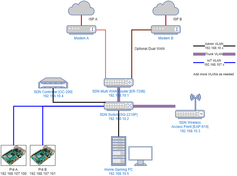
Diagram 1: Current LAN Design
-
Part 1 - Preparing the Perimeter / Outer LAN (Refer to Diagram 1 for connection)
-
Launch Omada Web Console, Login as an Administrator. It is recommended to do this step locally and have the configuration PC directly connected to one of the OC-200 LAN ports. If desired, backup current configuration and save it to a USB Flash Storage
-
On ER-7206, modify LAN VLAN IP from Default. If the default IP address of 192.168.0.1 has been changed from default before, skip this step.
-
Settings > Wired Networks > LAN > <Under Action Column, “Edit” the LAN Profile>
-
Gateway/Subnet > 192.168.10.1 / 24 > Update DHCP Range
-
Make sure all LAN interfaces are checked
-
Save
-
-
Inter-connect Gateway, Controller and Switch A SG-2210P
-
Connect SG-2210P Port 1 to ER-7206 Port LAN2
-
Connect SG-2210P Port 2 to OC-200 Port 1
-
Connect your configuration PC to OC-200 Port 2
-
Optional: Connect your EAP-610 to SG-2210P Port 7
-
-
At this time, it is important to follow the network IP as per the diagram, or make sure all SDN network devices have a reserved or static IP.
-
192.168.10.1 - ER-7206
-
192.168.10.2 - SG-2210P
-
192.168.10.3 - EAP-610
-
192.168.10.4 - OC-200
-
-
Create IoT VLAN on ER-7206
-
Settings > Wired Networks > LAN > + Create New LAN
-
Name: IoT
-
LAN Interfaces: Checked all LAN ports
-
VLAN: 107
-
Gateway/Subnet > 192.168.107.1 / 24 > Update DHCP Range
-
Save
-
-
-
Assign VLAN 107 on SG-2210P
-
Devices > <Click on SG-2210P> > Ports >
-
Port 3 > <Under Action Column: Click Edit> Profile > IoT
-
Port 4 > <Under Action Column: Click Edit> Profile > IoT
-
-
Apply
-
-
Connect all the IoT Devices on Ports 3 and 4 to be assigned to VLAN 107 directly to the switch
-
Assign VLAN 1 on SG-2210P
-
Devices > <Click on SG-2210P> > Ports >
-
Port 8 > <Under Action Column: Click Edit> Profile > LAN
-
-
Apply
-
-
Diagram 2: New LAN Design

-
Part 2 - Preparing Inner LAN Router/Gateway (Refer to Diagram 2).
-
Connect this Switch A SG-2210P Port 8 to WAN port of Gateway B ER-605
-
Connect a PC directly to the WAN/LAN3 port of Gateway B ER-605, the right-most LAN port usually works.
-
Launch a Web browser, and enter 192.168.0.1 to access the web console of Gateway B ER-605
-
Create Username and Password
-
Login
-
-
Prepare Gateway B ER-605 to be discovered and adopted by OC-200 at Perimeter site
-
System Tools > Controller Settings > Inform URL/IP address > 192.168.10.4 (this is the Controller’s IP address)
-
Save
-
-
-
Part 3 - Creating Perimeter and Inner LAN Sites
-
On the Omada Web Console, create / modify site
-
Click Sites > + Add New Site
-
Site Name: Inner
-
Country/Region:
-
Time Zone:
-
Application Scenario:
-
Username:
-
Password:
-
Apply
-
-
Rename and/or Modify the other Omada site to Perimeter (or Outer)
-
-
-
Part 4 - Building the Inner LAN
-
Make sure the Inner LAN is selected. The new Gateway can not be adopted to the current site with the existing ER-7206 Gateway.
-
Sites > Inner LAN
-
-
Adopt Gateway B ER-605. You may need to “Retry” a couple of times to get this new Gateway adopted. Make sure to use the username/password you created on Steps 2.3. If the Gateway does not appear after more than 5min, check your cable and/or check the Controller Inform URL/IP Address (refer to Step 2.4).
-
Devices > <Under Action Column, Click the “Adopt” Checkmark>
-
Enter user name and password created on Step 2.3
-
-
Configure Gateway B ER-605 to make it fully Omada-SDN compliant
-
Settings > Wired Networks > LAN > <Under Action Column, “Edit” the LAN Profile>
-
Gateway/Subnet > 172.16.0.1 / 24 > Update DHCP Range
-
Advanced DHCP Options > Option 138 > 192.168.10.4 (this is the Controller’s IP address)
-
Save
-
-
-
Connect Switch B SG-2210P to Gateway B ER-605
-
Transfer your PC’s connection from Gateway B ER-605 WAN/LAN3 Port to Switch B SG-2210P Port 2
-
Connect Switch B SG-2210P Port 1 to Gateway B ER-605 right most WAN/LAN3 port
-
Wait and keep refreshing the Devices tab of the Omada web console, until the new switch shows up for adoption. If the switch does not appear after more than 5min, check your cable and/or check the DHCP Option 138 (refer to Step 4.3).
-
Devices > <Under Action Column, Click the “Adopt” Checkmark>
-
-
Connect any other Omada network Devices (i.e. EAPs) to the new switch and adopt all devices. At this time, it is important to follow the network IP as per the diagram, or make sure all SDN network devices have a reserved or static IP for the Inner site.
-
Create Home VLAN on Gateway B ER-605
-
Settings > Wired Networks > LAN > + Create New LAN
-
Name: Home
-
LAN Interfaces: Checked all LAN ports
-
VLAN: 10
-
Gateway/Subnet > 172.16.10.1 / 24 > Update DHCP Range
-
Save
-
-
-
Using Omada Web Console, find an available Port from Switch B SG-2210P, configure it to “Home” Profile.
-
Devices > Select SG-2210P > Ports > <Under Action Column: Click Edit> Profile > Home
-
Apply
-
-
Connect all your clients to this “Home” port. It should have an IP from 172.16.10.x range
-
-
-
Part 5 - Testing
-
From your PC connected at Switch B SG-2210P at the Inner LAN site, ping any IP on the IoT network i.e. 192.168.107.1. Note, if you have a Windows PC as a test device connected to IoT VLAN, you may need to turn off the Firewall to have ICMP working. The expected result is that all devices at the Outer LAN are reachable unless an ACL is in place to prevent such from happening.
-
From your PC connected to IoT VLAN, ping any devices that are behind the Gateway B ER-605 Gateway i.e. 172.16.0.x, or 172.16.10.x. It should time out
-
Short Version Videos:
-
Part1 - https://youtu.be/VTrg2ecGetA
-
Part 2 - https://youtu.be/gQW0kvN_too